This project started up sometime in 2019 when DIY stuff was more of a side hobby. It was also a learning process for me and a project to work on with my father which we would come back to every now and then (while building other circuits in between sessions). I soon decided that it was time to get serious and really focus on finishing the sequencer and we got to work. Now it is almost complete and I would like to share the process from here on.
Unfortunately there was no proper documentation of the start and mid section of the project but it is still at an interesting build stage.
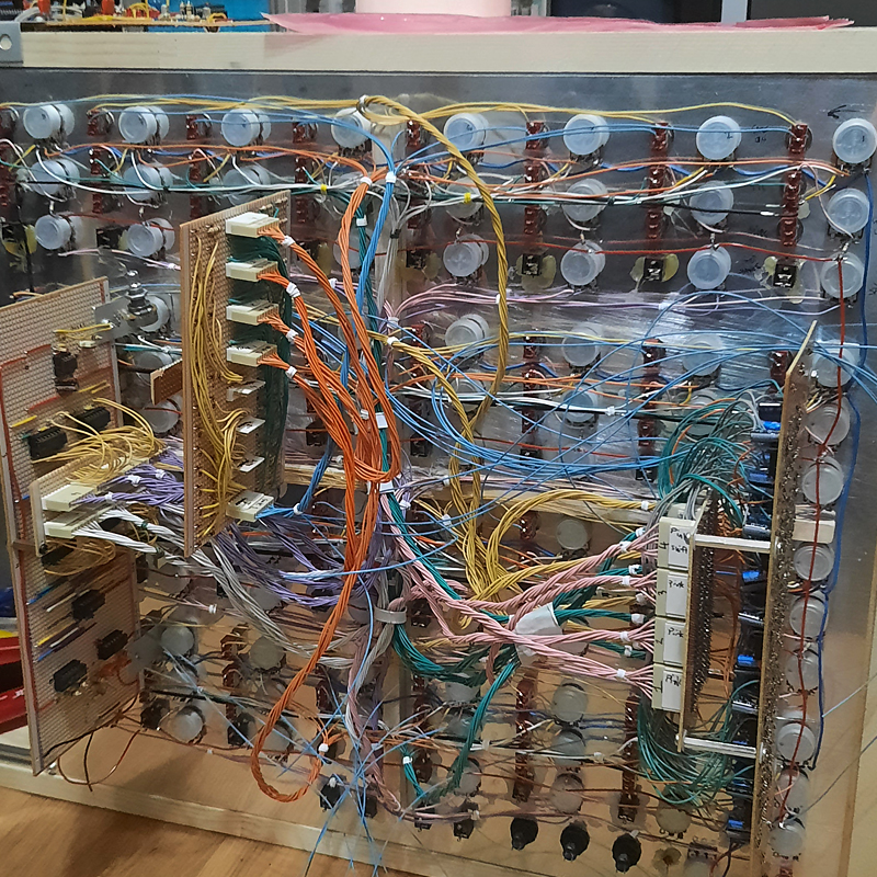
Here is how it currently looks:

The image below shows what each step will look like on the front panel (I promise to upload a much better photo soon). Every step has 3 potentiometers, 3 switches, an LED and a jack which together will be able to control Pitch, Gate Length, Note Shift, Gate on/off, Tie and Slide. The LED is the step indicator and the jack is for step length. The top left section in the box is step 1.
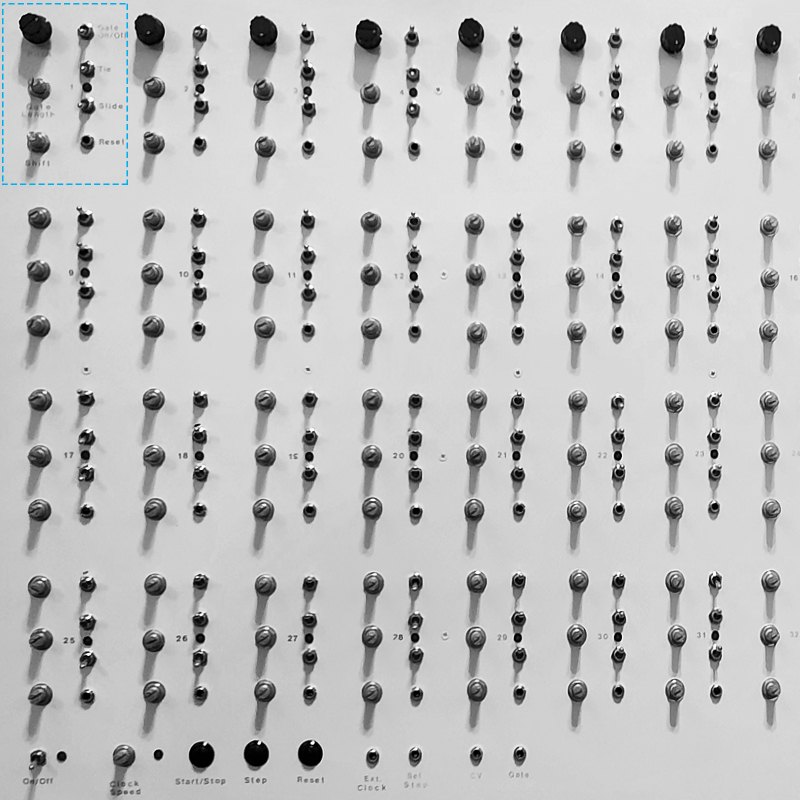
The sequencer is based off of the usual Baby-8 circuits you can find all over the internet which rely on the 4017 decade counter IC. Chaining them is fairly easy when following the circuit in the manufacturer specs. The slide circuit is based off of the TB-303 slide, which is a genius design in general.
At the bottom is the On/Off switch, Clock Speed pot, Run/Stop/Reset buttons and jacks for the external clock input, step length jack and CV/Gate outputs.
Before I continue I would like to share my mini failure with the panel design. I originally gave it a matte white coat and then used dry-transfer Letraset for all the text. I was pretty happy with how it looked and took it outside for a clearcoat varnish. I stupidly used the white matte spray again and ruined my labeling. This is why the text looks so bad in the image above.
After a few minutes of cursing and head shaking I called it good and gave it the layer of varnish. Since it is a prototype the mistakes are accepted.
The next part I want to share is the original approach to all the wiring. It was unplanned and a bit of a mess, which I eventually changed to a more compact and “simple” plan. All work has been done on stripboards so I wanted to make a breakout board which I could easily connect to the main boards. It was a good idea but also a rather unnecessary one.
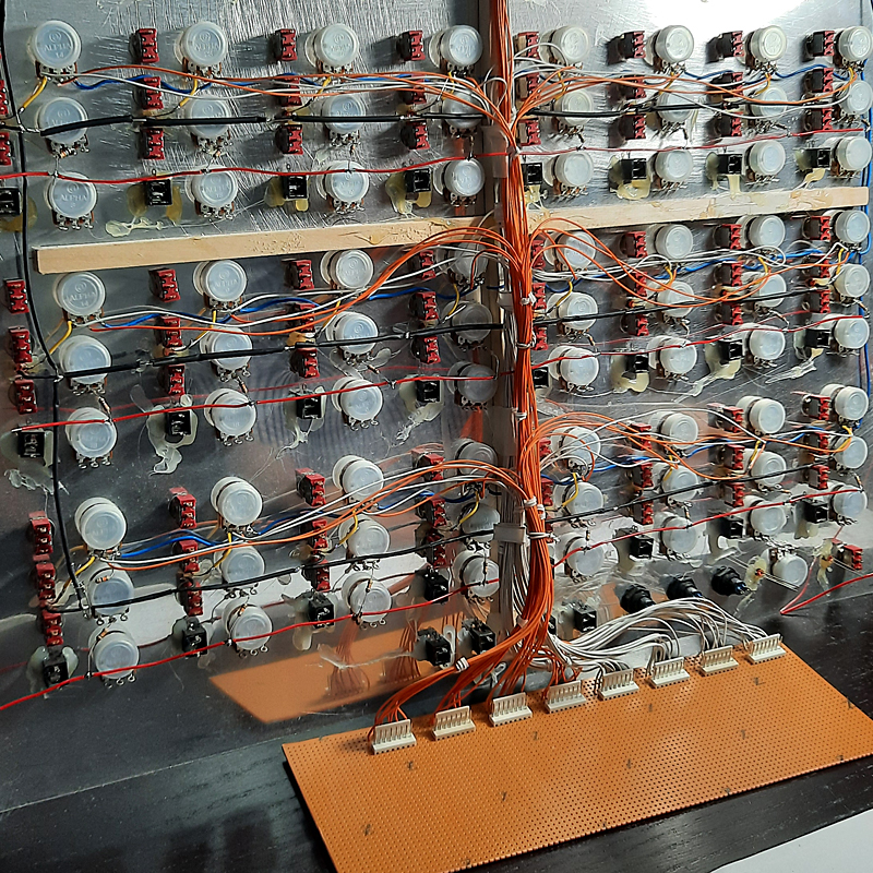
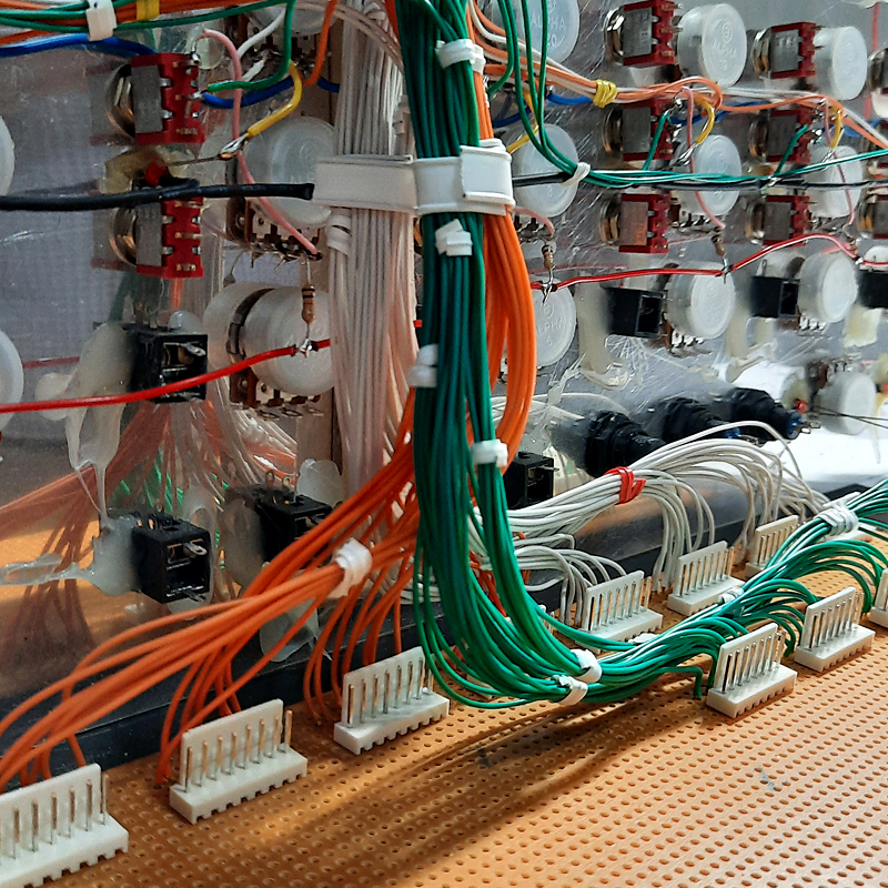
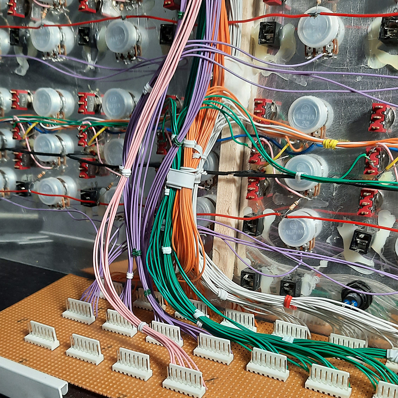
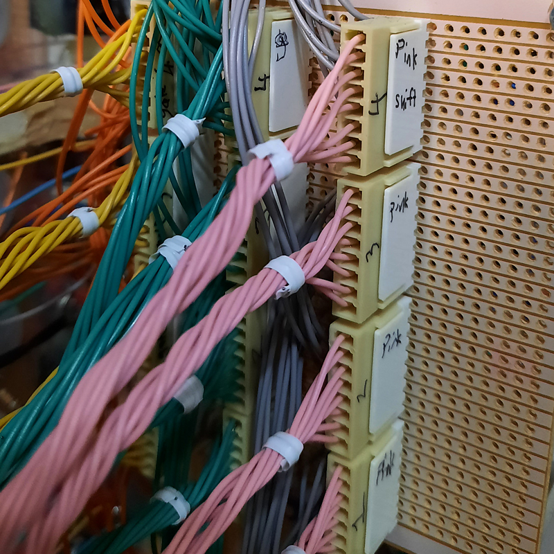
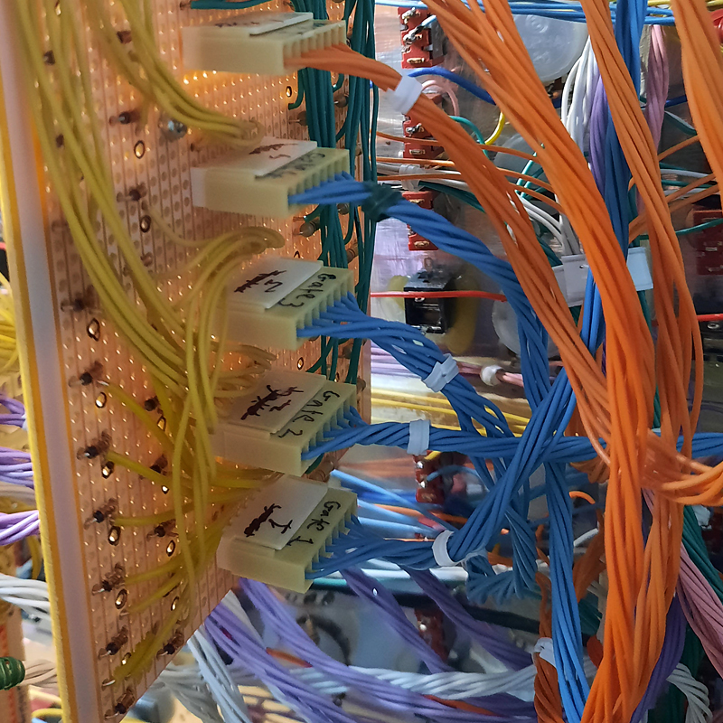
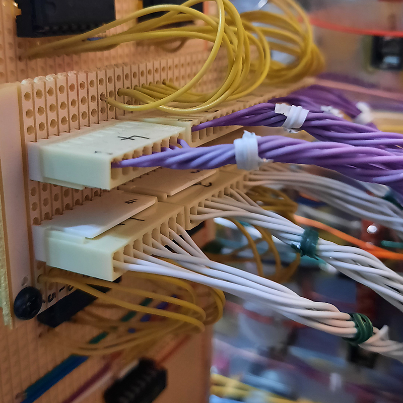
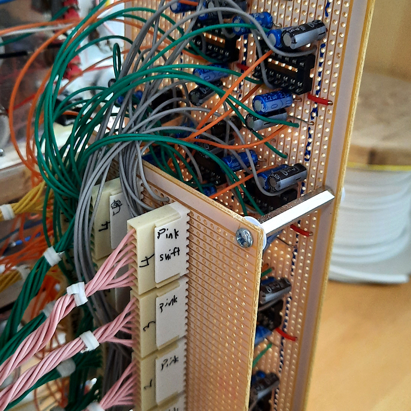
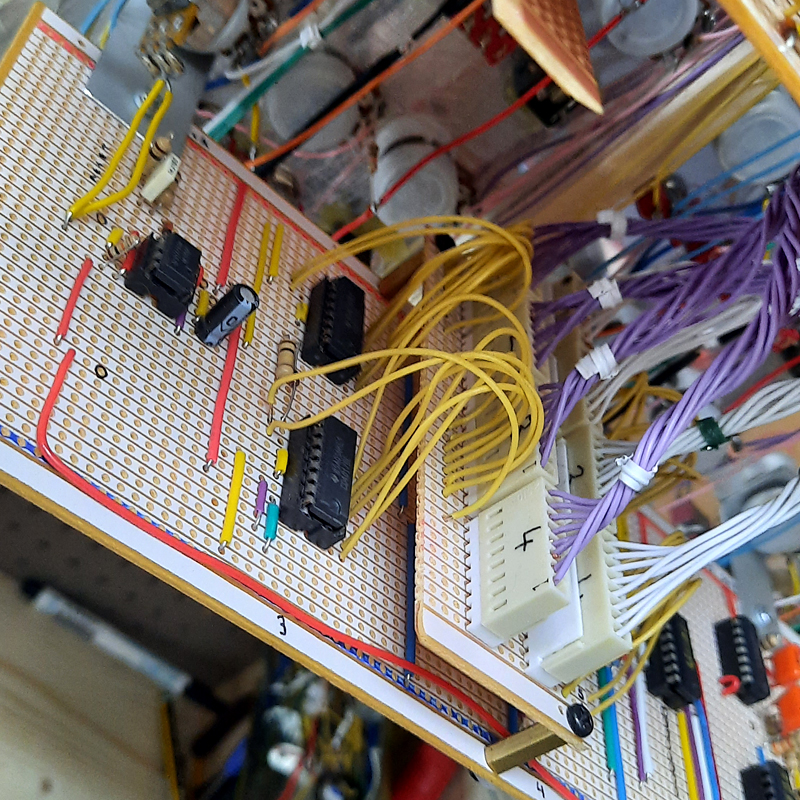
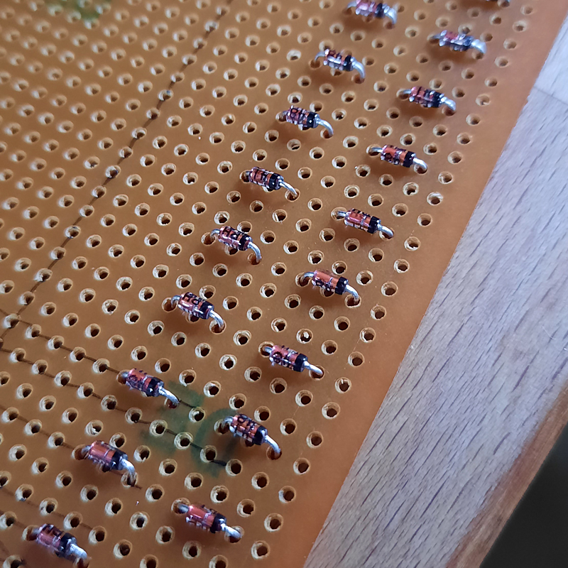
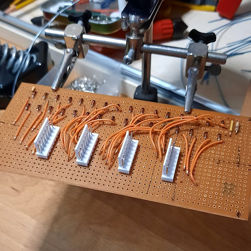
I decided it would be better to have all the wiring go directly on to the stripboards instead, so I made some “PCB holders” and screwed them on to the boards, attaching them to the potentiometers which are tightly fastened on the main panel. Here are some nice close ups of the wiring.
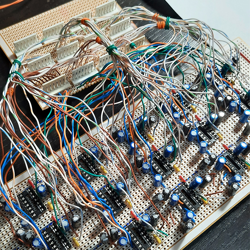
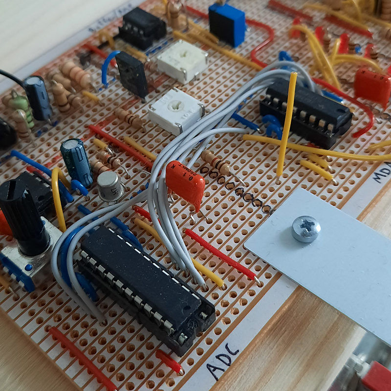
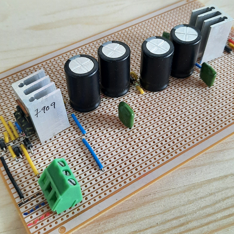
The final images in this post are the other boards not yet attached. The first one is the main buffer/quantizer/output board, the second is the power supply and the last two is for the slide section which I need to add in at a later stage. The quantizer section was inspired my the first video posted by Moritz Klein, which you can see here.
All in all things are going very well. There is still a lot of wiring to be done and some final adjustments here and there. Then all the trim pots have to be adjusted so I can get a 3 octave range on each pitch pot. Also, hopefully everything works when turning it on for the first time!
Only time will tell… more coming soon.
